Language: English












Rehabilitation of Reinforced Concrete Beams
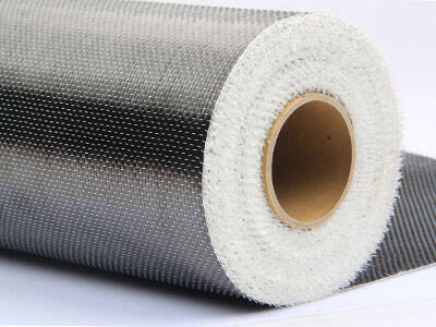
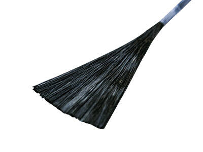
Carbon Fiber Reinforced Polymer(CFRP) Sheet
The adopted solution combines externally bonded steel plates (for primary beams with significant strength deficit) and carbon fiber reinforced polymer (CFRP) sheets (for secondary beams, joint zones, and shear-critical regions).


Project Overview
This project involves the structural rehabilitation of an existing multi-story reinforced concrete (RC) frame building. The structure consists of RC columns, primary and secondary beams, and cast-in-place reinforced concrete slabs — a typical cast-in-situ RC frame system common in university buildings from the late 20th and early 21st centuries.


Problems
Change of building function — lab equipment, library stacks, or new functional requirements may exceed the original live load capacity
Member deterioration — long-term environmental exposure, concrete degradation, or reinforcement corrosion
Deficiency identified in assessment — structural audit revealing insufficient shear or flexural capacity in key members

Solution
The adopted solution combines externally bonded steel plates (for primary beams with significant strength deficit) and carbon fiber reinforced polymer (CFRP) sheets (for secondary beams, joint zones, and shear-critical regions).
1. Primary Beams — Externally Bonded Steel Plates (Flexural rehabilitation)
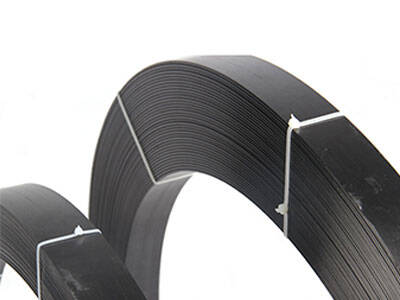
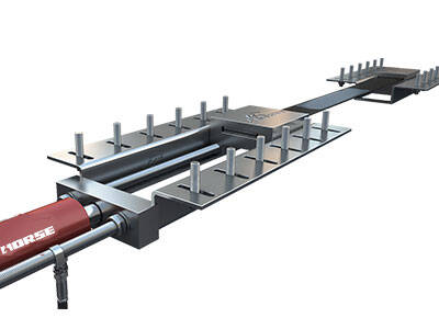
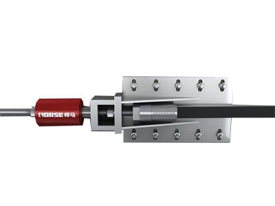
Application method: Steel plates are epoxy-bonded to the soffit (bottom face) of primary beams, oriented along the longitudinal span direction.
2. Secondary Beams — CFRP Sheets (Flexural rehabilitation)
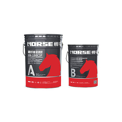
Application method: Unidirectional CFRP sheets are impregnated with epoxy resin and bonded to the soffit of secondary beams, with fiber direction aligned parallel to the beam span.
3. Beam-Column Joints — CFRP U-Wraps (Shear rehabilitation)
Application method: CFRP sheets are applied in a U-shaped configuration around the beam cross-section at supports and joint regions, with fibers oriented perpendicular to the beam axis (vertical direction on the web faces).
4. Beam Intersection Zones — CFRP Cross Sheet
Application method: CFRP sheets are applied in a cross-pattern at primary-to-secondary beam intersections, addressing the complex stress state at member junctions.
Advantages of the Combined Approach
| Design Aspect | Steel Plates | CFRP Sheets | Combined Benefit |
|---|---|---|---|
| Strength gain magnitude | High — ideal for heavily loaded primary beams | Moderate to high — efficient for secondary members | Optimized per member requirement |
| Stiffness contribution | Very high — reduces deflection significantly | Lower modulus than steel per unit thickness | Steel handles stiffness-critical members |
| Added dead load | Moderate — steel is heavy | Near zero — critical for existing structures | CFRP limits overall weight increase |
| Installation speed | Slower — heavy plates, mechanical anchors | Fast — lightweight, hand-layup | Parallel installation on different members |
| Corrosion resistance | Requires protective coating | Inherently corrosion-resistant | CFRP preferred in aggressive environments |
| Cost per unit strength | Generally lower for large gains | Higher per kg but less material needed | Cost-optimized by member type |